

SUPER SLENDER
Cal. 1000 - 1003
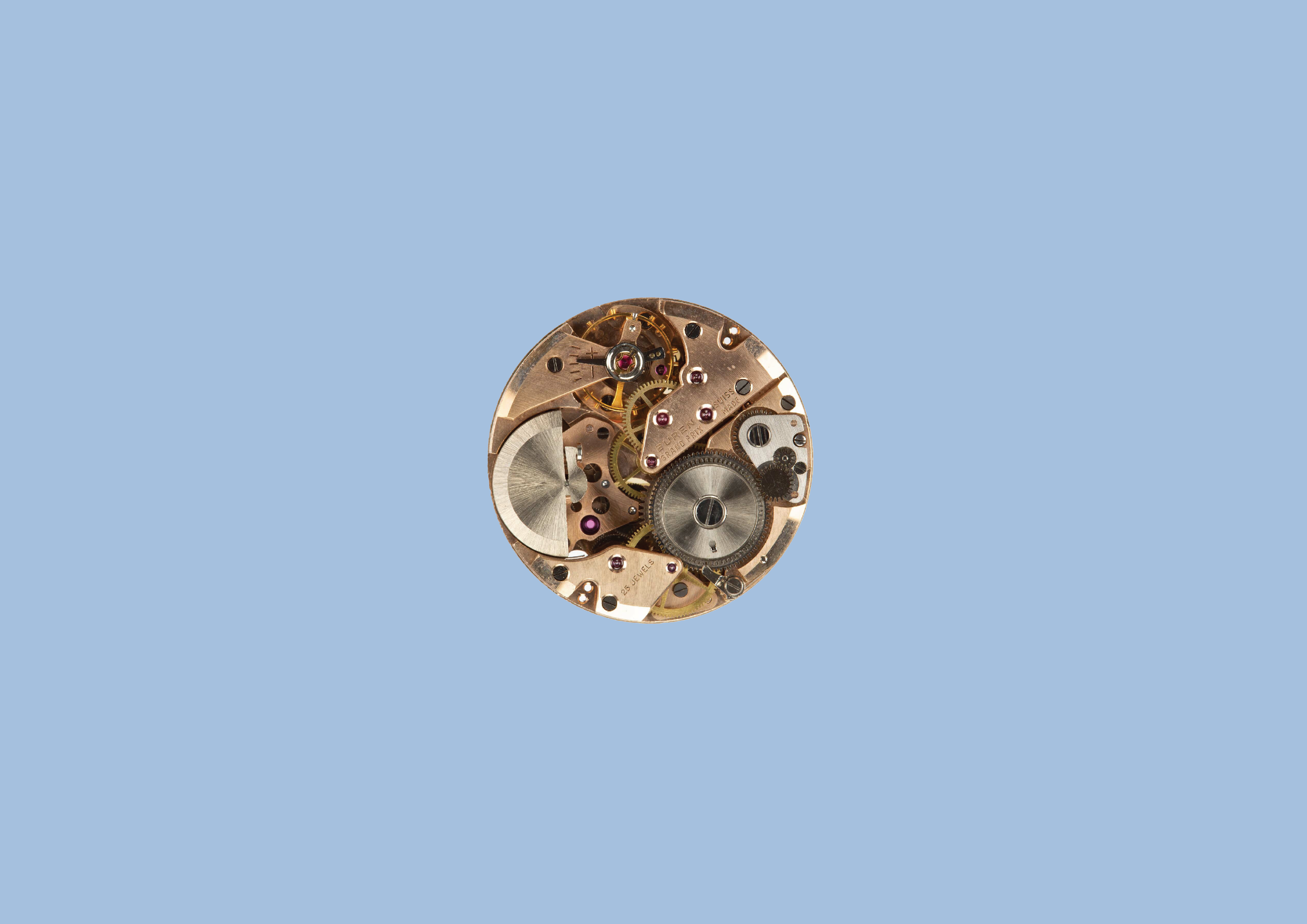
In 1954, through the efforts of Hans Kocher, our chief designer, we patented a micro-rotor winding system named PLANETARY ROTOR® that finally saw production in 1957. The small rotor integrated at the same level as the rest of the movement, which allowed us to produce the flattest automatic watches at the time.
Discover how we developed the SUPER SLENDER® movement introduced from the patent application that started in 1954 to the completed project in 1958. It took more than 4 years of research and development to achieve the famous SUPER SLENDER® automatic movement with unprecedented reliability.

THE FIRST
1951
The calibres 1000 and 1001 produced in series from 1957 onwards, measuring only 4.2 mm and 4.8 mm thick with date. The watch was called SUPER SLENDER®. The integrated flywheel in the movement allows for the production of movements that were surprisingly flat for the time.
By shrinking the diameter of the rotor, to fit within the radius of a comparable movement, and locating this rotor in the same plane as other components of the movement, we avoided the need to place the rotor behind the movement.
At the time we also licensed its technology to other companies, the INTRAMATIC® for IWC, Baume & Mercier, Bulova, Breitling and Hamilton, used in the “Thin-O-Matic” line. After a patent dispute, we also began to license its micro-rotor technology to Universal Geneve.
CH317534
STATEMENT OF INVENTION N°317534
MAI 6, 1954, 6¼ p.m.
Class 71e Buren Watch Company s/A. (Switzerland).
The object of the present invention is a mass for a self-winding watch. This mass is characterised in that it comprises a first pendulum element capable of pivoting with respect to the frame of the watch and whose movements are intended to be transmitted to the barrel arbor, and at least one other pendulum element pivoting freely in the first of said elements, in order to transmit to it an initial impulse intended to facilitate its starting during a change of position of its pivot axis.
One embodiment of the mass, object of the invention, is shown, by way of example, in the accompanying drawing.
CH317534 BUREN WATCH COMPANY SA

CH329804
STATEMENT OF INVENTION N°317534
MAI 6, 1954, 6¼ p.m.
Class 71e Buren Watch Company s/A. (Switzerland).
Watch with automatic winding by the rotary displacements of a mass. The object of the present invention is a watch with automatic winding by the rotary displacements of a mass.
This watch is characterised in that the material of said mass is housed at least approximately in a circular cylinder sector, and in that this mass occupies at least part of a cylindrical space of the movement cage, delimited in elevation by the extreme planes of the plate and the upper bridges of the watch train.
However, given the small dimensions of this ring, it often happens that it is lost by jumping out of the tweezers, when it is kept in a stretched state. The object of the invention is to avoid this inconvenience by providing a ring capable of being put in place and removed without the risk of losing it, that is to say by avoiding any excessive tension of this ring when handling it.
CH329804 BUREN WATCH COMPANY SA

PROSECUTION
1955
Universal Genève applied for their patent in May of 1955. The micro-rotor movement in the Polerouter series was nearly identical in design specification to the SUPER SLENDER®. Buren won the patent infringement case, and U.G. had to pay Buren royalties for each microrotor it used until their patent was granted. During that early period, Universal Geneve was apparently required to label their movements as "patent pending", and, as a result of the dispute, were not able to record the actual patent until May 15, 1958.
"... Eleven months later, Universal requested patent protection for a similar construction, the so-called Polerouter. Negotiations were successful, and Universal agreed to pay Buren a reduced license fee in the amount of four Swiss francs per movement. In 1959, the two companies co-signed a licensing contract with Complications SA. Its new self-winding caliber, which was named Piaget 12Pl ..." Power or Aesthetics, by Gisbert L. Brunner (Watchtime, October, 2006).
CH331595
STATEMENT OF INVENTION N°331595
DECEMBER 12, 1955, 6½ p.m.
Class 71e Buren Watch Company s/A. (Switzerland).
Device on watches for fastening the winding shaft It is known that winding shafts of watches are fastened by means of the setting lever or the setting lever block connected to it, which engages in a groove of the winding shaft formed by two flanges.
The setting lever itself is fixed by the setting lever screw from the movement side, so that in order to be able to turn this setting lever screw, the movement side of the movement must be accessible. This does not apply in particular to movements intended for installation in cases where the back and the middle part of the case are in one piece.
Since the winding stem can usually only be inserted after the movement has been installed in the case, difficulties arise with these cases in that the movement side is covered after installation in the case and the setting lever screw can no longer be turned.
CH331595 BUREN WATCH COMPANY SA

CH335486
STATEMENT OF INVENTION N°335486
NOVEMBER 6, 1956, 6¾ p.m.
Class 71h Buren Watch Company s/A. (Switzerland).
Watch with automatic winding by the rotary movements of a mass. The mounting, in a watch that is automatically wound by the movements of a moving mass, of an alarm mechanism comprising a hammer intended to strike against part of a bell-shaped gong extending above the bridges of the watch movement, could hardly be envisaged until now, since the usual moving masses, consisting of a heavy sector pivoted in the center of the movement of the watch and surrounding it, do not allow access of the striking hammer to said gong, unless a winding mass is used, the movements of which are confined to a determined sector of the movement.
On the other hand, if one tried to pass the striking hammer under the winding mass, it would be necessary to provide the bell forming the striking gong with a rim so high that there would not be enough space left. in height to ensure the fixing, of the movement of the watch in the middle of the box, unless you make a much thicker watch.

CH335486 BUREN WATCH COMPANY SA
CH333258
STATEMENT OF INVENTION N°333258
NOVEMBER 23, 1956, 6½ p.m.
Class 71h Buren Watch Company s/A. (Switzerland).
Alarm clock The subject of this patent is an alarm clock in which the movement and the striking mechanism are actuated by the same mainspring. The clock-watch according to the present invention is characterized in that said mainspring is automatically charged by the movements of a mobile mass.
One embodiment of the alarm watch according to the invention is represented schematically and by way of example in the appended drawing, in which FIG. 1 is a plan view of the mobiles of the watch movement and of the automatic winding mechanism; fig. 2 is a section of some elements of FIG. 1; fig. 3 is a section of the watch through the axes of the moving parts of the automatic winding and striking mechanisms; fig. 4 is a plan view of the mobiles of FIG. 3, and fig. 5 is a bottom view of a detail of FIG.

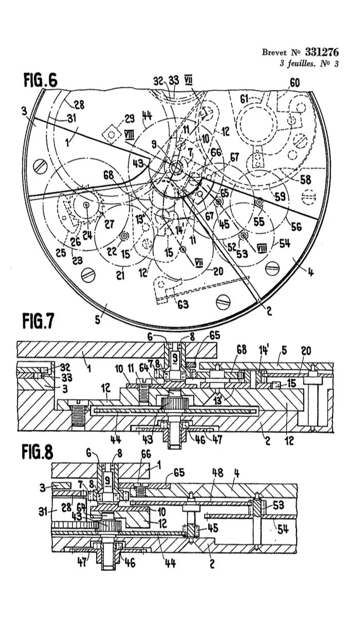
CH331276
STATEMENT OF INVENTION N°331276
NOVEMBER 27, 1956, 4¾ p.m.
Class 71e Buren Watch Company s/A. (Switzerland).
Self-winding watch The subject of the present invention is a self-winding watch with a rotor formed of a plate of at least approximately constant thickness, in which the gear train and the self-winding mechanism are arranged between the plate and the bridges.
This watch is characterised in that the upper surfaces of the barrel, gear train and automatic winding bridges are located in a plane and in that the rotor moves above this plane.
The appended drawing shows, by way of example, two embodiments of the watch forming the subject of the invention.


CH331278
STATEMENT OF INVENTION N°331278
DECEMBER 12, 1956, 5 p.m.
Class 71e Buren Watch Company s/A. (Switzerland).
Rotor for automatic winding watch and process for its manufacture In watches with automatic winding by rotor, that is to say in which the winding mass can make complete turns around its axis rotation, the movement of the rotor can be caused by two distinct causes.
The first lies in the accelerations to which the user's arm is subjected, for example when the latter makes gestures, walks or is on board a vehicle. Due to its inertia, the rotor follows the movement of the watch in which it is mounted with a certain delay, so that there is a relative movement of the rotor with respect to the movement of the watch.
The second cause lies in the changes in position of the watch, without taking into consideration the speed or the acceleration imparted to the watch, the rotor rotating around its axis under the sole action of gravity.
CH331279
STATEMENT OF INVENTION N°331279
DECEMBER 12, 1956, 5 p.m.
Class 71e Buren Watch Company s/A. (Switzerland).
Rotor for self-winding watch. The subject of the present invention is a rotor for a self-winding watch, comprising a mass of heavy metal and a pinion secured thereto, the mass being fixed to a plate in ordinary metal, coming in one piece with a barrel driven on a shaft integral with said pinion. This rotor is characterised in that the heavy metal mass has in plan the general shape of a sector of a circle and extends to the immediate vicinity of said barrel, which it partially surrounds.
The appended drawing shows, by way of example, three embodiments of the rotor forming the subject of the invention. fig. 1 is a top plan view of the first embodiment. fig. 2 is a view in axial section. Figs. 3 and 4 are sectional views, similar to FIG. 2, of the other two embodiments.

CH345849
STATEMENT OF INVENTION N°345849
MARCH 26, 1958, 5¼ p.m.
Class 83a Buren Watch Company s/A. (Switzerland).
Timepiece with automatic winding. The subject of the present invention is a timepiece with automatic winding by a mobile mass mounted cantilevered and whose shaft pivots in the frame; this timepiece is characterised in that the mass is secured to a clip, part of which is in the form of a split washer, the hole of which is passed through without clearance by the outer end of the shaft of the mass, this washer having a substantially radial arm against which a control member mounted on the mass rests, such that, when said control member is actuated, the gripper closes and tightly encloses the shaft, thus securing the mass angularly and axially with his tree.
The drawing shows, by way of example, one embodiment of the subject of the invention. Only what is necessary for understanding the invention has been shown in the drawing.
fig. 1 is a top view of the moving mass.
fig. 2 is a sectional view taken along the line II-II of FIG. 1, this view also showing the bearings of the shaft: of the mass, secured to the frame of the timepiece.
Figs. 3 and 4 are respectively sectional views taken along lines III-III and IV-IV of FIG. 1.

CH347774
STATEMENT OF INVENTION N°347774
MAI 10, 1958, 1¾ p.m.
Class 83a Buren Watch Company s/A. (Switzerland).
Simple date watch. The object of the present invention is a simple date watch, which comprises an indicating member normally held in angular positions determined by an elastic member and a drive member, which is actuated by the movement of the watch and which advances said indicating member by one step once every twenty-four hours.
Known watches of this type generally have a drive member engaged with a wheel keyed on the hour barrel wheel, so that this drive member completes one revolution in twenty-four hours. Said drive member carries a pin or a finger intended to advance the date indicator member, consisting of a ring with internal teeth.
A first drawback of these watches lies in the fact that the drive member remains engaged for several hours with the internal toothing of said ring, so that the date is practically out of service during all this time. Furthermore, when the hands of the watch are moved backwards, it may happen that the date indicator is inadvertently driven in the same direction.
Finally, when it is a question of resetting the date indicator to the date, after a month of less than 31 days or after stopping the watch, it is necessary to operate the hands of the latter several times around the dial, unless the watch is equipped with a corrector pusher acting on the date indicator.


Super Slender Cal. 1000 BUREN WATCH COMANY SA

CH343911
STATEMENT OF INVENTION N°343911
FEBRUARY 21, 1959, 11½ a.m.
Class 83a Buren Watch Company s/A. (Switzerland).
Timepiece movement It is often claimed that the electric watch, that is to say the one whose balance wheel has its oscillations maintained by electromagnetic means, ensures a greater precision of rate than the mechanical watch. In judging the matter, the following three factors should be considered:
a) Constant force of the pendulum drive;
b) Impulse as short as possible, at the moment when the pendulum has its greatest speed
c) Maximum moment of inertia of the pendulum, for a pendulum of determined weight and diameter.
Show Alternative Close
In the case of the balance wheel with electromagnetic drive, condition
a) is relatively well fulfilled. On the other hand, condition
b) is much better satisfied by the lever escapement of mechanical watches. Finally, with regard to condition
c), the balance wheel with electromagnetic drive is always provided with coils or similar elements, so that its weight is necessarily quite high; consequently, for an equal diameter and an equal moment of inertia, the balance of a watch with electromagnetic maintenance is heavier; in other words, for the same weight and the same diameter, the balancer with mechanical maintenance has a moment of inertia greater than that of the balancer with electromagnetic maintenance.
These reflections show that there is a priori no reason to believe that the electric watch makes it possible to obtain greater rate precision than the mechanical watch.


BUREN DIVER
Buren diver’s first model circa 1960 with matte black original dial, luminous indexes and hands, elapsed bezel, and screw down crown 32 X 37mm. Distinctive wide hands. Powered by 17 jewel manual wind movement with sweep seconds. Replacement screw down crown bears a “fleur de lis” raised logo.
Cal.unknown BUREN WATCH COMPANY SA

CH1290761
STATEMENT OF INVENTION N°1290761
NOVEMBRE 7, 1961, 6½ p.m.
Class 83a Buren Watch Company s/A. (Switzerland).
Automatic winding watch movement. The subject of the present invention is a self-winding watch movement comprising a winding mass housed entirely within the limits of the movement cage, the barrel, an escapement mechanism with regulating balance wheel, a first gear train between the mass and the barrel and a second gear train between the barrel and the escapement.
A watch movement of this type is described in Swiss patent No. 329,804. The fact that the winding mass is entirely housed within the limits of the rage makes it possible to give the movement described in this patent a particularly thin thickness.
Despite this arrangement of the winding mass, however, it can be seen, both in the movement described in the patent and in known movements comprising a similar mass, that there is still a lot of space lost above or below the winding weight and the barrel. This comes from the necessary interweaving of the moving parts of the movement.
The latter in fact comprises three large mobiles: the winding mass, the barrel and the balance, which are placed one beside the other and which occupy, in plan, the greater part of the movement. It follows that the other mobiles of the movement must be placed at least partly above or below one or the other of these three large mobiles, in particular the barrel and the winding mass.


